5 Axis Machining – Blade/Impeller

Moving the Shop Floor into the Digital Age
September 5, 2019
CAMWorks Automates 3 Axis Mold Programming
June 25, 2020

CAMWorks 5 Axis Machining Blade/Impeller Machining

CAMWorks 5 axis capabilities

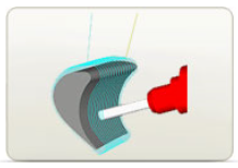
CAMWorks now being popular in small job shops to produce complex part on their 4th and 5th axis machines. Here is an example of a 5 axis blade/impeller machining with the ‘Easy to Use and Powerful Multi-axis CAM Capabilities’. CAMWorks has the workflow supporting a smart manufacturing capabilities with a full suite of advanced multi-axis features. 5 axis simultaneous milling capabilities and advanced turning and mill-turn capabilities are available into a single integrated easy to use system. Thanks to it’s seamless integration with SOLIDWORKS, the design and manufacturing model become one in the same. All of the CAM data is stored directly inside the SOLIDWORKS part and assembly files and the CAMWorks tool-paths update automatically to design changes.

MultiAxis-Machining

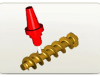
 Machine Complex Parts

CAMWorks allows you to take advantage of 4/5-axis machines that provide greater productivity, equipment flexibility and quality. CAMWorks 4/5 axis simultaneous machining programming software allows the user to create tool-paths across complex shapes that could not be machined on 3 axis machines. This includes high-performance automotive port finishing, impellers, turbine blades, cutting tools, 5 axis trimming, and undercut machining in mold and die making. CAMWorks 4 Axis simultaneous machining is designed for complex rotary applications such as camshafts, extrusion screws and blades with benefits including:

  • Reduced Cycle Time
  • Improved Surface Finish
  • Extended Tool Life

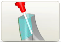
Shorter cutting tools can be used since the tool can be tilted to adjust the angle between the cutter and the part. Increased rigidity of shorter tools allows you to take advantage of the high-speed options in CAMWorks to machine at higher speeds with no loss in accuracy. The result is better surface quality and reduced finishing time. Generating 5 Axis swarf tool-paths instead of traditional 3 axis tool-paths can result in fewer cut passes and improved surface finish. CAMWorks multi-axis machining can save time and cut down on mistakes. By optimizing the angle between the tool and the surface, it is possible to achieve a constant chip load and a high feed-rate at the contact point. The result is improved surface finish and extended tool life. Parts that previously required multiple setups can be machined in a single setup with simultaneous control of the rotary axis. In addition to saving time, this also cuts down on mistakes that might be made during multiple setups.

CAMWorks Multiaxis machining provides a powerful set of features and cutting strategies to meet the machining requirements of diverse applications.

  • Support for multiple tool types including flat, ball, hog nose, tapered and undercut tools such as lollipop and key-way.
  • Cutting strategies for swarf cutting, profile contouring, engraving, grooving and machining deep corners and cavities.
  • The tool orientation while in contact with surfaces is completely user-controlled. Options include the ability to define tool orientation relative to the surface normal. To get a good finish with a 5 Axis machine, the tool should have a specific angle to the surface. This tilt angle can be fixed, a variable angle based on the current normal vector of the surface or user-defined from points, lines or curves.
Collision-detection-5-axis
  • Collision detection looks at each tool-path and the surfaces to decide if the tool tip, tool shaft or holder is colliding. The check is done at each calculated tool position. Groups of surfaces can be defined, each with its own avoidance strategy.
  • Roughing options include multiple cuts normal to the surface, multiple cut depths along the tool axis, full 5 Axis plunge roughing and adaptive roughing.
  • User-defined limits for the machining area and tool angles on several planes for increased flexibility.
  • A lag angle can be set between the end of a flat or hog nose tool and the surface, which results in a face milling condition that reduces the number of cuts in shallow areas.
  • Undercut areas can be machined using 3, 4 or 5 Axis strategies.
  • Rest machining options determine if CAMWorks generates tool-paths to remove remaining material based on an STL file or a calculated work-in-process (WIP).
  • Options to take advantage of an existing stock geometry to minimize air cuts during roughing operations.
  • User-defined options determine how CAMWorks handles gaps: gaps in surfaces can be ignored and machined without retracting the tool, the tool can be moved back to the rapid plane and skip the gap or the tool can follow other surfaces.
  • Numerous options provide simple and easy trimming of vacuum-formed or fiber reinforced plastic parts.
  • Multi-axis laser tool-paths can be created to trim sheet material in difficult to reach areas, for pre-production runs where stamping require trimming, or when single set up trimming is required for production speed.
  • Area roughing options can be set for impeller and blisk floor finishing and roughing, and for slots on cylinders.
  • A user-defined area can be defined to contain the tool-path.
  • Tool-paths can be generated as separate threads and in separate processes. Multiple tool-paths will generate simultaneously and at the same time the user can continue working in other areas or on other CAM models.
  • Tool-paths can be copied and rotated to create full rotation symmetric operations (for example, impeller machining).

­ ­

Comments are closed.

Subscribe to Blog

  • This field is for validation purposes and should be left unchanged.

X